Girder Forks
After almost four years and with a huge amount of distribution of the Chopper Builders Handbook pages at other web sites it seems pretty clear that most people interested in building a chopper frame have enough information. Now it's time to start looking at the other components of a bike and of course the most important and third most expensive part is usually the forks.
Over the past forty years I've ridden bikes with all kinds of forks having all kinds of rake and trail and I always come back to the classic girder as my personal favorite for both choppers and road bikes.
To my way of thinking a 'custom chopper' with hydraulic forks is a misnomer since how can a custom bike have a set of store bought hydraulics which no matter how much they costs are really the bottom of line as far as suspension goes. Some builders also have a problem with this approach so in an attempt to make their rides 'look' more like a real custom they'll add in a some Springer forks. Unfortunately such forks are also pretty much off the shelf items. On the other hand if the builder went so far as to make his own frame why not make his own forks and this is where Girder forks start to appear since they are the highest end of the suspension system spectrum.
This section of the site which we first posted on Oct. 9, 2005 may end up being the largest single section of the site that will ever be posted since it is going to be an extremely technical section and will eventually require a ton of pictures and diagrams before it gets fully fleshed out. This will be an ongoing work so don't take the initial pages as the final pages as I imagine we'll be updating this area fairly often as comments and critiques start to roll in.
As mentioned elsewhere Girder forks are
probably the best front-end suspension system ever invented. In fact many
experts believe that Girders, or their derivatives, will eventually be the ideal
front suspension design used on all cycles in the future. For some insights into
this future we encourage readers to examine the works of Foale and Britten but
in the mean time we have to keep this section of the manual focused on the older
or more traditional interpretation of Girder forks as found on most choppers.
Girder forks took their name from the
classic structural shape of the Girder Truss or Girder Beam used primarily in
bridge or roof construction since the fourteenth century but perfected during
the late 1800’s. This shape represents the most fundamental engineering
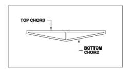
application of ‘triangulation’ as seen in Figure 1 below.
Figure
1
In such a structure the bending forces on
one of the spans that puts it in compression are resisted by the spans on the
opposite side that then are placed in tension. Such structural elements resist
forces that can come from either side and can be arranged horizontally, as in a
bridge, or vertically, as in a tower.
Basically the assembly is comprised of a
single compression member and one or more tension members with struts connecting
the members at midpoint. You can actually build a girder truss with a rigid
compression member, represented by the ‘top chord’ in the diagram above, and
wire cables as the tension members, represented by the ‘bottom chord’.
An excellent example of modern day girder
trusses in action can be seen in sailboats where the mast is the compression
member and the wire rope side stays are the tension members. The very same
engineering principals that keep these masts from bending apply to motorcycle
forks.
A truss or girder can be hundreds of times lighter than a solid structural member intended to resist the same forces. It was the invention and perfection of steel girders that made structures like the Eiffel tower possible back in 1889.

Figure
2
Not coincidental is the fact that almost
all bicycle makers immediately adopted the ‘triangulation’ method for frame
and fork construction at the same period in history but that’s another story.
The biggest
advantage of a Girder, for chopper applications, as compared to Springers or
telescopic forks is that Girders can be both extremely light and extremely
strong at the same time. They are relatively inexpensive to build and can be
constructed in very wide variety of shapes and sizes to suit individual tastes.
In fact there are very few if any design constraints so the limits of a Girders
appearance is only restricted by the builders imagination.
While this is a
blessing to many talented fabricators it is also a hindrance to the average
home-based bike builder as it is this very flexibility of design that makes
Girder layout relatively complicated compared to Springers for instance.
Where one can
pretty much build a ‘universal’ Springer design that will work on a wide
variety of frame types most good Girders are custom engineered and fabricated
for particular frame geometry. This is the reason that almost all
‘mass-produced’ Girders that have been on the market over the past thirty
years have had little appeal to the public since they usually didn’t work well
on most bikes and many people had very bad experiences with poorly setup Girders
that simply didn’t suit their particular bike. On the other hand those rare
few who just happened to have frames that matched the geometry of the fork
makers master-frame had nothing but praise for the handling quality of their
front-ends. It was a hit or miss proposition and the vast majority of buyers
were unwilling to take a gamble so Girders took a back seat to Springers for
most custom builders. Even today with some new mass-produced Girders on the
market the same situation still exists.
My first
introduction to girders involved building rigid forks out of angle iron that
could be used on ‘rollers’ in a shop that did a lot of custom work. We’d
just hack together crude rigid girders and yokes to the appropriate lengths so
the fabricators could move uncompleted bikes around the shop and the owners
could at least have a better visual ideal of what their rides would look like.
Some of these lash-ups actually saw the road under power before the final fork
selections were made.
Just a few of the many fork shapes girders can use are pictured in the diagram below. Click on the picture for a larger image.
 |
Figure 3
Girders when viewed from the front can be just as diversified as the side view designs shown above.
 |
As mentioned
above Girder forks are inexpensive to build. It is entirely possible to buy all
of the materials and components for a first class set of forks for under $250 in
most parts of the country. Depending upon the techniques and methods of
construction very few special tools or equipment are needed and improvisation
can lead to many creative solutions to bypass the need for expensive machine
work if you’re on a really tight budget. There is also tremendous opportunity
for those out there who have access to aluminum casting equipment and some
imagination. The sky is the limit as to what a person can come up with.
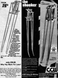
Figure 4 is a series of advertising scans sent in by site visitors taken from magazines of the sixties and seventies.
Figure
4
Many of these old
Girders were made from bent solid stock and were pretty poorly welded with
extremely crude link connections, which certainly didn’t do anything to help
with user acceptance of the basic design. To make matters worse backyard
builders just copied these old crappy ‘off the shelf’ designs to the point
that almost all people came to believe that a Girder was just about the last
type of front-end that you wanted on a bike.
What makes
Girders complicated isn’t the design of the Girder Beams themselves but the
geometry of the trees, links and attachment points which can be almost
infinitely arranged to provide all types of trail and affect other elements of
handling such as anti-dive and anti-squat to name only two. Some have said that
Girder forks are an engineers ‘heaven’ but a builders ‘hell’.
People who
don’t care for Girders to begin with are very quick to point out that on a
well-designed Girder the trail will change by a whole 3/16 of an inch when the
forks are cycled from maximum compression to maximum extension for about 3.5”
or more of total suspension travel. Detractors cite this as a horribly dangerous
characteristic of Girders.
 |
What they forget
however is that trail change, on a well-designed set of hydraulic-telescopic
forks as they move through 3.5” of travel is a whopping 2”or more! This is
why most serious road racing engineers are looking to girders instead of trying
to improve hydraulic forks. This also shows that most people commenting about
fork geometry don’t know what they’re talking about in the first place.
 |
The above
paragraphs of course refer to static changes in trail. The dynamic changes in
trails as the frame dips and rises in response to suspension travel are of
course more dramatic as the effective rake angle is dynamically changing but
even then the Girder is far superior in performance.
Plain and simple,
Girders handle better than any other fork style you could possibly use; if
properly designed and constructed. Poorly designed or poor built Girders however
can be real nightmare.
Unfortunately
this section of the manual can’t tell you how to build a ‘perfect’ set of
Girder forks since a well-designed set is truly custom tailored to a particular
bike but it can get you started in the right direction and save some wasted time
in your development efforts.
All of the data
and design information that follows concerns designing and building a set of
forks that are intended to be used on frames having geometry very similar to our
so-called ‘standard’ designs. In other words, for frames with a neck height
of about 33” and a neck rake of about 40 degrees. The diagram below
illustrates the key dimensions needed to start designing a typical Girder fork.
If your bike is within plus or minus 2” or plus or minus 2 degrees of these
specs our published Girder plans will work with only minor customization. If
your bike is above or below these tolerances you’ll have to do some
experimentation. Believe me it’s well worth it to get a good set of girders on
your ride. Once you’ve had the experience you’ll never use any other type of
forks again.
 |
Before we go any further I’d like you
to understand that it is impossible for me to know how much your particular bike
weighs or how much you yourself weigh. I cannot know what the spring rates will
be for the shock you eventually decide to purchase or what size wheel and tire
you’ll eventually be running. For this reason I strongly suggest that you
assemble your entire front end with only tack welds until you can actually mount
it on your personal frame. Once the forks have the final weight on them you can
adjust the location of the shock mounts and link lengths to optimize the
geometry for your unique setup.
This ‘cop-out’ turns many away from building a Girder since they immediately think that the project will simply be to complex to be feasible but this is false reasoning. A lot of builders put together complete fork mockups from plumbing pipe, conduit and even wood before deciding on the final connection and attachment points for a good custom-designed front-end. Nothing ‘good’ is ‘easy’, and building a ‘good’ set of forks will always require a lot of work. Those looking for the quick fix can buy a set of $1500 hydraulics and be riding on crap all day long not having any idea of what good forks are really like. As they say ‘ignorance is bliss’.
There are at
least three schools of thought about how to attach the links to the upper and
lower yokes and forks on Girders. Old-school folks like to use the method where
the yokes and forks each have a long ‘pin’ or ‘shaft running through the
yokes and forks in bushings and the links attach at each end of this shaft. In
this setup the shaft rotates in the bushings and the links are rigidly attached
to the shafts.
The more modern approach, though not to say a better approach, is to replace the shaft with shoulder bolts or machined pins and have the links themselves pivot in bushing on the rigidly mounted bolts or studs.
A low-cost way to fashion ‘pins’ or ‘studs’ is to plug weld a section of solid drill rod of a suitable diameter inside a piece of DOM tubing. You leave enough of the drill rod exposed on each end for the bushed links to slip on to and then thread the last inch or so for a nut and washer.
The third
approach involves building the links and cross-members as an integral unit where
the left and right fork legs are separate components and then the entire
assembly is tied together with continuous shafts at the upper and lower fork
pivot points. This hasn’t been a popular construction method in the past but I
personally think it has the greatest potential for ‘modern’ chopper forks.
Two of the more popular link attachment methods are illustrated in the two exploded view diagrams below. Click on the pictures for larger images.
 |
 |
All of
these basic methods work just fine and it is largely a matter of what you
personally prefer and what equipment you have on hand to do the machine work
that makes the final determination on which way you decide to go.
Regardless of
what style of attachment you decide to use it must be understood that in all
girder designs the weak link in the system, structurally speaking, is in the
attachment point of the suspension links with the pivot points. More
specifically it is the diameter of the pivot shafts or the shoulder bolts that
you have to be concerned with.
The weakest point
of any threaded shaft is where the threaded portion meets the unthreaded area
and most engineering manuals publish the shear strength of this junction for
various types of material.
In the case of
girders the shaft material is usually mild steel with a tensile strength of
around 36,000 pounds per square inch and the shear strength for various shaft
diameters is as follows:
3/8” shaft shear strength in the shaft proper = 10,280 psi
3/8”
shaft shear strength at the thread neck = 3,970 psi
1/2” shaft shear strength in the shaft proper = 18,350 psi
1/2”
shaft shear strength at the thread neck = 5,985 psi
5/8” shaft shear strength in the shaft proper = 28,785 psi
5/8”
shaft shear strength at the thread neck = 11,140 psi
3/4” shaft shear strength in the shaft proper = 41,515 psi
3/4”
shaft shear strength at the thread neck = 17,800 psi
It’s pretty obvious that the larger
diameter shaft and thread is the way to go if you want to build strong
front-ends but there is a ‘practical’ limitation where you run up against
‘looks’ vs. ‘build-ability’ and in the world of Choppers ‘looks’
pretty much overrides other engineering constraints.
You also run up
against the wall of ‘engineering impossibility’ where an engineer will tell
you a particular design idea will fail mathematically but the very same design
has been in actual road use for decades without any problems. So who is right?
In the world of
choppers we very often have to fall back upon empirical knowledge gleaned from
years of trial and error experiments to find the correct answers to many
questions. History has shown us that the typical maximum ‘normal’ load
imposed on most motorcycles (catastrophic crashes excluded) is about ten times
their dry weight with a ‘safety factor’ of three.
If you look at
the loads on a girder, or even a springer, from an engineering standpoint, based
upon the rule-of-thumb sited above, it
appears as if the minimum bolt or shaft diameter needed is .75” for typically
encountered maximum road impact (failure) loads but in the real world thousands
of bikes have been riding the pavement with .5” shafts and bolts for decades
with no problems.
From where I
stand today, based upon the average weights of choppers being built in this
decade I would be willing to say that a minimum solid shaft or shoulder bolt
diameter should be .625” for either springer rockers or girder linkages which
equates to a .5” threaded segment diameter at the minimum.
For a girder
application this means using a shaft or shoulder bolt with a .625” diameter
that terminates in a .5” diameter threaded portion at the connection point.
This will give you a breaking strength of 5,985 psi at the intersection of the
shaft and the thread neck, (which is the weak juncture) at each connection
point, of which there are four.
Is this a
‘safe’ assumption? Well let me say that there are perhaps thousands of old
girders out there riding around using .5” shoulder bolts or pivot shafts that
only have .375” threaded studs and as far as I know none have failed to date
in regular road use. Some of the old 640-pound Indian Chiefs had .5-inch shafts
bend and the factory switched to 9/16” and they had no more problems. If you
have a habit of hitting curbs or doing wheelies you’re probably at risk even
using the larger diameter specifications. Each and ever builder has to fabricate
his or her components to their own personal level of safety and sanity. What we
specify herein works for our own level of what I consider ‘average’ road
conditions which may be different than your own interpretation so in the end the
fabricator has to be the final judge as to what is safe and what is not. To be
very honest I personally have no problem riding rather long Girder forks using
only .375” studs and half-inch shafts but I know my limitations.
There is another
very important point we have to bring up however and that is exactly how the
loads are to be placed on any particular shaft, shoulder bolt or regular bolt
for that matter. The forgoing paragraphs assumed that the fasteners in question
had loads applied in what’s sometimes called a ‘single shear’ scenario.
Imagine for a moment that you screwed a big lag bolt into one of the wall studs
in your garage so that half of the shaft was sticking out of the wall and then
you gave a downward blow with a hammer right on top of one of the flats of the
hex head. In effect you applied a ‘load’ at the head of that lag bolt and
the ‘shearing’ point was where the screw met the stud. The wood stud
supported half of the bolt and the other half of it was unsupported, just
hanging out in the air. This is the ‘single-shear’ installation. Now imagine
another situation where you screwed the bolt into two studs that are about 6”
apart so that both the threaded tip and the hex head itself are completely
embedded in the wood. Now in this instance if you whack the bolt right in the
middle of it’s length, in the space between the two studs, it will resist the
force of the blow at both ends and have twice the resistance to bending. This is
called a ‘double shear’ installation.
If you look at a typical clevis and pin you will see a good example of a ‘double-shear’ engineering application. The pin is supported at both ends and the load has to be applied right in the middle. This is exactly the same type of connection method you should endeavor to use in building the link connections for a pair of girder forks.
Continued
on page II
.............................................................................................................

| Main Page | Terms of Use | Security and Privacy | FAQ | Contact |
Copyright © 2003-05 Chopperhandbook.com, Chopperbuilders.net, All Rights Reserved