 |
Girder Forks
There really
aren’t any limitations on how long Girder links can be. Some sport bikes with
cutting edge technology use links that are almost 18” long. Old Indians used
links that ranged from 4 to 4.75 inches. 60’s era ‘customs’ had links that
were in the neighborhood or 5 to 5.5 inches long. I personally think that
shorter links handle better and try to keep my designs in the range of 4 to 4.5
inches center to center of the attachment points.
Link length is
closely related to not only the diameter of the shock you select but also the
effective travel length of the shock. The links have to be long enough to
provide clearance for the shock while at the same time permitting the forks to
cycle completely through the shocks full range of motion, which is usually in
the area of 3.5 to 4.5 inches of total travel from maximum compression to
maximum extension.
Keep in mind that just like springer rockers the Girder links act as levers and have a significant impact on ‘perceived’ spring rates. Long links have a lot of leverage and can use much stiffer springs than shorter links. The relationship of the lower shock pivot point and link length is crucially interconnected from a design standpoint.
In an attempt to correct problems with trail encountered by many riders who happen to have a set of improperly designed girders on their bikes some have resorted to using upper and lower links having different lengths. It is true that using unequal length links can be used to advantage on specially design fork geometries but it is a poor system to use on the vast majority of bikes. Some ‘unexpected’ and ‘unwanted’ handling characteristic may result if you don’t know what you’re doing. Just to give one simple example of a common situation, note that in the figure below, the lower links are 5” long and the uppers of 4” long. You’ll see this quite often in the real world. What you don’t see however is the rather radical changes in trail that occur as such links cycle through full shock compression and extension that can easily change the trail a full 3” every time you hit a bump.
|
In general almost
all unequal length parallel link configurations will ‘bind’ at certain
points in the travel arcs and even though the rider is unaware of it every time
the links overcome one of these binding points the forks and links bend to
compensate which eventually leads to stress fatigue of the components.
Using unequal
length links that don’t have the pivot points properly arranged can also lead
to a catastrophic situation where one of the links will go ‘over-center’ and
actually lockup the entire fork assembly.
Equal length parallel links will always give the best handling characteristic on typically driven street choppers and it’s my personal opinion that experimentation with unequal length links be left for your road racer where you really do want certain changes in geometry at specific points in the suspension travel.
This last statement may lead one to believe that the links have to be 'straight' or 'parallel' to the ground but in reality the link 'pivot points' themselves only have to be parallel and equal to one another. The links themselves can be shaped like almost anything including 'L's' or 'U' shapes, swords, spears, boomerangs, lightening bolts, etc., etc.
Unfortunately advertisers on Madison Avenue invented the phrase ‘shock-absorber’ and in reality the Brits have a far better term to describe what the modern day ‘shock’ really is and that’s a ‘damper’.
The only role
that a shock plays in the world of suspensions is to ‘dampen’ spring
oscillation and not to ‘absorb’ impacts from the pavement. You can easily
drive a car or a bike without shocks but if you hit a bump you’ll have a
roller-coast ride until the springs get through doing their thing. On the other
hand you can’t drive a car or a bike without springs since you’ll just
destroy the shocks when you hit the first bump in the road.
In the old days
Girders had a central spring, usually progressively wound, and a pair of
friction shocks mounted on either side of the lower pivot points. Even back then
most builders realized that the friction shocks ‘sucked’ to say the least so
when newer hydraulic shocks appeared on the scene they were quickly adapted. The
Vincent builders placed a hydraulic shock up between the links and added long,
narrow shielded springs to the forks as seen in figure 4 below. Their set up was
called a ‘Girdraulic fork”.
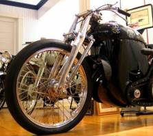
Figure
4
Fortunately
nowadays we’ve got dozens of coil-over shock combinations to choose from.
Unfortunately most don’t fit in between the narrow constraints of chopper
forks to well since the diameter of the coils are simply to large to clear the
steering neck and the fork cross-members.
A full eighty
percent of all of the effort you will put into building your Girder forks will
be in selecting an appropriate coil-over shock (or shocks) and then deciding on
the ideal mounting points for that particular shock between the top yoke and the
lower fork cross-member.
You will have to experiment with various
spring rates over time until you come up with the ideal solution for your
particular bike. No two bikes are alike and depending upon the location of the
center of gravity for your particular ride you might need a shock with a spring
rate as low as 70 pounds to as high as 300 pounds.
Over the years
I’ve become pretty suspicious about ‘published’ spring rates from various
shock manufacturers so take anything you get from spec-sheets with a grain of
salt. For example one popular mountain bike shock supplier has a unit with a
so-called 180 pound spring rate but if you look at the little .25” diameter
coils that are almost 2” on center vertically compared to the much beefier
Koni with .375” diameter wire stock at 1 inch on center for the same
‘published’ rate you just have to wonder who’s closer to the fact of the
matter.
We bought a very
narrow shock from Italy that was rated at 150 pounds with 3.5” of travel all
in a package that was only 1.75” in diameter but when we received it the real
rate was more like 8 pounds since we could easily compress it to full bind with
just body weight alone.
I’m sorry to
say it but as to shock selection you’re completely on your own as we’ve
bought and tried several dozens of units from various makers and to date I’m
still not completely satisfied that we’ve found a starting point that we can
recommend.
For those wanting
to experiment we want to remind readers that spring ‘rate’ is expressed in
the terms of ‘X’ pounds needed to compress the spring at it’s unloaded
(free) height by one inch in length. For example if we have a spring with a rate
of 100 pounds it will take a weight of 100 pounds to compress it one inch in
length or height and a weight of 200 pounds to compress it two inches in length
or height and so fourth. If we have a spring that is 10 inches long having a
‘rate’ of 100lbs./in. with no weight on it and we put it in a set of forks
bearing 200 pounds of the bikes weight it will compress two inches under static
load leaving only eight more inches to use for real suspension.
Unfortunately
however very few springs have nearly this much effective range before they
‘bind’, or reach the point where the coils stack up against one another and
in effect become a solid mass. In shock salesman terms this is the ‘coil
bind’ position or point of maximum compression. Keep in mind however that
springs ‘stretch’ as well as ‘compress’ so what we’re looking for,
ideally, is a spring that will compress around 1” when the front weight of the
bike is on it (about 2/5th the bike total weight actually) but still gives us
around 2.5” more compression before binding. Such a spring will also stretch
2.5” (probably significantly more) at full extension. In other words we’re
looking for a spring with fairly small diameter coils having a rate of around
200 pounds that has at least 2.5” of compression room before the bind point
for a light chopper.
Don’t bother
looking at car coil-overs for possible Girder springs since they are usually far
too large in overall diameter to fit between the forks and the steering stem.
Instead look at small coil-overs for ATV’s, golf-carts, motor scooters (Vespa),
mountain-bikes and rear shock units for small displacement imported swing-arm
bikes. Right now one of the old rear coil-over shocks on my Honda 750 is looking
pretty good but it’s really about one inch to long for what I want.
For those who
want specifics before they start a design project we’ve found that coil-over
shocks having an overall (fully extended) length approaching 11.5” are a good
starting point. At load condition these units typically are near 10” in length
and shorten to around 8.0” at maximum compression giving you about 3.5” of
‘effective range of motion’. You can fit almost anything you find however by
playing around with the location and angles of the shock mounting tabs so
don’t be discouraged if you can’t find the ‘ultimate’ unit for your
particular application right from the start. Sooner or later you’ll stumble
across a unit that’ll be perfect.
Keep in mind that
girder shocks can take of advantage of unequal valve rates and that you need
more dampening on the extension stroke than on the compression stroke for a
smoother ‘perceived’ ride. This is just the opposite of what you’d
normally expect. Always keep in mind that the spring is really doing the
suspension work and that shock is just dampening the spring, which seems to be a
hard fact for many Americans to grasp after fifty years of brainwashing about
shocks.
Dual shocks look cool but they double your costs and believe me when I say you’ll never find two identically performing units unless you pay a premium for a so-called ‘balanced’ or ‘matched’ pair. Normally only one of the units is really doing the work and the other just follows along playing catch-up. If you just have to have multiple shocks why not try to run four ultra-mini coil-overs in some unconventional mounting position that nobody’s done yet.
The tubing you
decide to use is based exclusively on how long the forks have to be. Whatever
you do please don’t use solid rod in a set of girder forks. On the one hand
it’s over-kill as to weight but under-kill as to strength.
Short forks, less
than 24” in overall length can be constructed from stock as small as .75”
O.D by .095” wall. Forks up to 32” in overall length can be safely
constructed from 1” tubing with a .120 wall. Forks 32 to 36” in overall
length need to be 1” O.D. by .134” wall. Forks 36 to 40” in overall length
need to be 1” O.D by .156” wall material. For forks over 40” in length you
really need to go to 1.125x.156” tubing at least for the front or primary
legs. These suggestions are based upon not having any unsupported (non-gusseted)
single spans over 28” in length. Of course these suggestions also assume that
you’re building a lightweight chopper. If you’re building one of the new-age
680 pound sleds some folks call a chopper then I can’t possibly give you a
starting point as to tube sizes. Short wheelbase heavy bikes need more beef in
the forks as more weight is on the front end. Long chops with the motor well aft
of the midpoint of course need less meat up front since the center of gravity is
further to the rear.
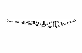
If you keep the unsupported lengths of tubing short, by using intermediate struts, you can very easily build forks up to six feet long from 3/4"x.083" tubing and they'll be incredibly strong. An example of such construction is shown below.
One of the weak points in girder forks is the inability to adequately resist torsion forces that are applied in a line perpendicular to the steering stem axis. If you can visualize your bike parked with the tire wedged in between two huge concrete blocks while somebody pulls on a twenty-foot cheater bar welded to the fork tree you can understand what I’m talking about. Under extreme road conditions the wheel axle acts like a long lever and wants to ‘twist’ the two fork legs in opposite directions. Of course such forces can be easily resisted if we had tension members that ran down the ‘outsides’ of the fork legs but we usually don’t. Instead we have to rely on having the main compression members (front fork tubes) large enough in diameter or thick enough to resist twisting as well as bending.
Common sense and
experience has to come into play when you are building any type of fork system.
The fabricator has to be responsible for putting together something that is both
safe and effective at the same time.
In this era of
the ‘lawyers’ many builders have fallen back on building massive over-kill
solutions for chopper front ends which is why we’re seeing Springer and Girder
forks with 1.5” diameter tubes which is simply ridiculous and we all know it.
I personally think that if a person is afraid of his or her own capabilities and
personal judgment then they shouldn’t be messing around with chops in the
first place.
Can you possibly
imagine some guy walking into an insurance company or a local law firm and
saying “ I’m a custom chopper builder and I want to build cutting edge,
balls-to-wall death machines but I don’t want to be liable for anything”.
Of course when he leaves the office his fully sanctioned, approved and safe frame specs for a chop is 2” diameter .25” wall frame tubing and 2” diameter .25” wall fork tubes. Do you want one of his bikes? If you want safety and sanity don’t mess around with choppers to begin with and don’t come crying to me for recommending something that broke down the line. You’re going to be the ‘builder’ so use your own judgment and build to you own personal levels of safety and sanity.
Before starting
to layout the design of your upper tree or yoke it’s a good idea to give some
thought as to how you’re going to mount the handlebars with respect what type
and size risers you’re going to use. Today there are basically two ways risers
on mounted to trees. One method of course is to just drill a couple of half-inch
holes, spaced 3.5” apart and just bolt the risers through the tree with ½-inch
by 13 socket head cap screws. A refinement on this method involves milling a
slight recess, having a diameter that matches the diameter of your riser, about
1/4-inch deep into the upper surface of the tree. This makes for a little
tighter and cleaner installation. Beware that not all risers have the same base
diameter and in fact some are elliptical, not circular, in cross section.
One problem with the methods outlined above and variants thereof is that the handlebars don’t have any type of vibration isolation and this bothers some riders. If you want isolated bars then you’ll have to use the big ugly rubber, or fancier polymer isolation bushing that set in big holes bored through the tree.
 |
The disadvantage
of the isolators is that the risers have to be set further forward on the tree
to allow clearance for the little dust covers and the steering stem dust shield
so the whole tree is therefore larger than it would have been otherwise.
Of course the
ultimate girder risers would be integral with the trees; that is welded into
position, with nice graceful sweeps back to the handlebar collars.
We typically
leave enough ‘meat’ in our standard tree drawings and patterns so you can
build them for either solid or isolated risers.
Continue to Part III................................................

| Main Page | Terms of Use | Security and Privacy | FAQ | Contact |
Copyright © 2003-05 Chopperhandbook.com, Chopperbuilders.net, All Rights Reserved